
Hacking a Fibre Optic Christmas Tree

Is your fibre-optic Christmas tree making an absolute racket?
It's no surprise because the motors used in most of them are absolute trash.
Perhaps it's time to make it 'smart' with addressable LEDs an ESP32 and WLED!
Like a lot of people, we have one those Christmas Trees that use fibre optic strands to create a lighting effect through the branches. These are pretty simple devices. All of the fibre optic strands are routed from the branches, into the 'trunk', ending in a pretty solid bunch at the bottom. A 12v halogen or LED spotlight points into the fibre optic bunch, lighting up the ends within the branches. A colour-changing effect is produced by a colour wheel that sits between the lamp and fibre optics, which is driven by a synchronous motor.
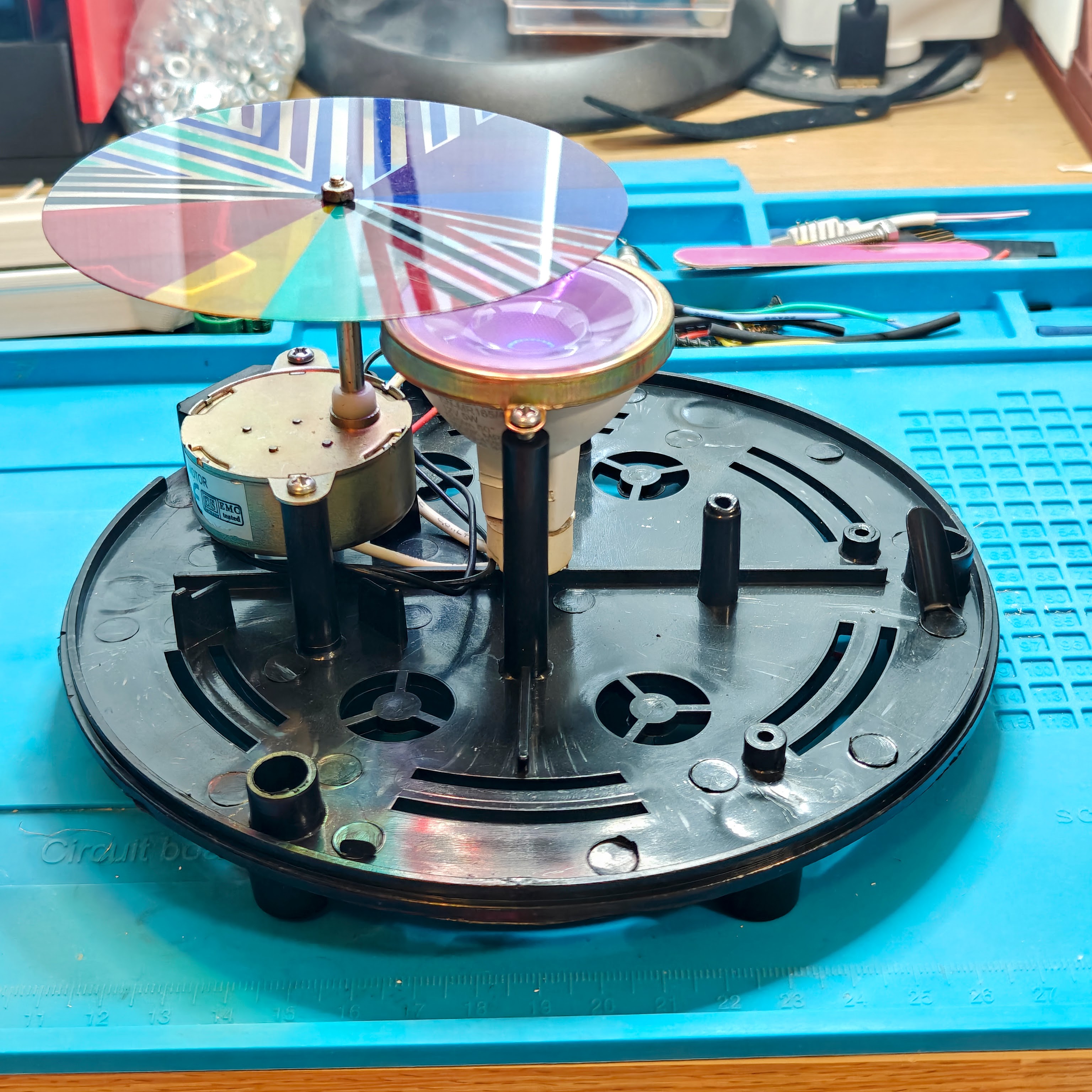
Now, these things a built to a price and, in my experience, use the cheapest components possible. On our tree, the synchronous motor had been noisy from day one and every year the tree was erected, it seemed to be getting louder. This year, it was so noisy that the rattling and grinding could be heard over the TV so it was time to do something about it!
I could have just replaced the motor with a better one but, there was still no guarantee it would be silent so I decided to investigate removing the lamp and motor assembly and convert the whole thing to something smarter using addressable LEDs and an ESP32 board running WLED.
Components and Design
The lamp diameter is around 35mm which 'sort of' matches the diameter of the fibre optic bunch. I've seen some people stick a 7 segment LED disc under the trunk but that would leave quite a bit of the tree unlit. A quick search and I found some 38mm 12 segment LED rings so, the idea was to put the 7 segment within 12 segment ring, lighting the whole of the tree.

I started off by stripping all the existing electronics from the base. Then, numerous measurements were taken so I could design some mounts for both the LED components and the ESP32 D1 Mini board that would control the LEDs. The mounting location of the original spot lamp was quite a bit lower than the socket for the fibre-optic trunk which was probably wasting quite a bit of light output so, during the design process, I raised the LEDs so they are only a couple of millimetres from the end of the trunk.
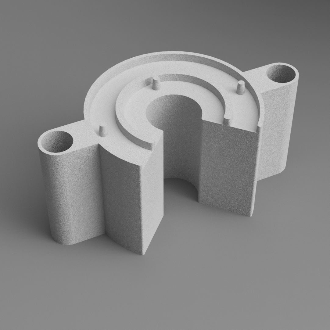

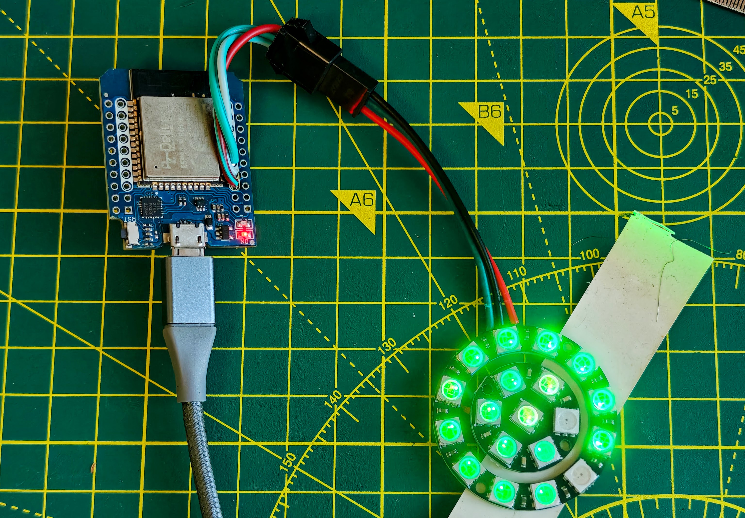
While the mounting parts were printing on the BambuLab A1 Mini, I prepared the D1 Mini by flashing it with WLED and soldering jumper leads between the LED rings, and connector pigtails to the outer ring and the ESP32 board. I then performed a quick test to see if everything was working prior to proceeding further.
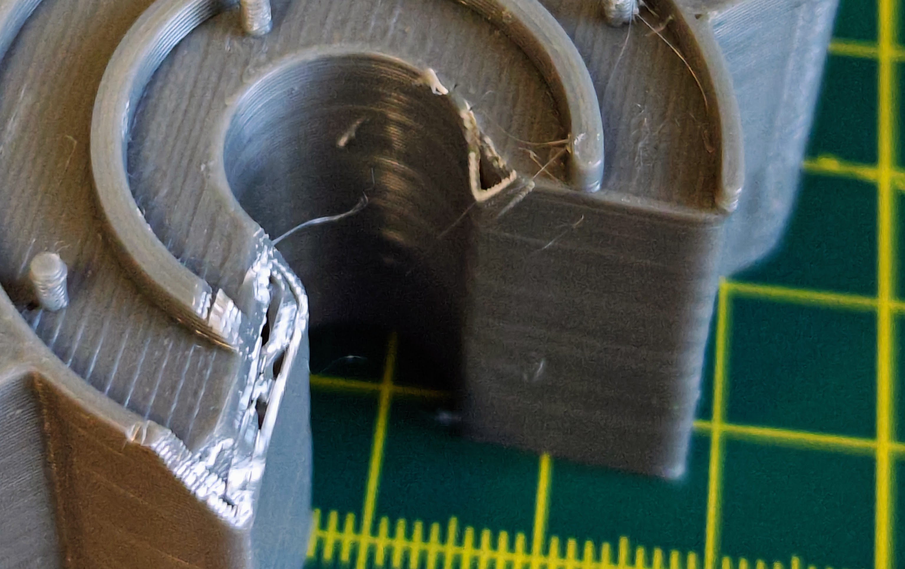
There was a bit of a cock-up during printing the mounts. First of all, I managed to print them in ABS instead of PETG because I didn't spot the wrong spool of filament was being used until it was too late! I had to nurse the print by continually turning off cooling (ABS shrinks if it's cooled too quickly), but I wasn't going to let it go to waste!
The prints weren't pretty because of this but, as long as they worked, I wasn't bothered as they would be hidden.

Next problem: Although I thought the quarter cutout on the LED mount would have allowed enough space for the solder pads and wires on the LEDs, they were catching in a couple of places so I had to perform a bit of manual adjustment with a craft knife.
Apart from that, everything was a great fit so I went ahead with mounting the components in the base of the tree, using the same screws used to mount the original lamp and lamp-holder.

As there are only 19 LED's in total, the absolute maximum power draw from the LEDs would be 3.9 watts (0.78 Amps) so it is perfectly acceptable to power both the LEDs and ESP32 from a standard 1A USB phone charger. A suitable right angle micro-usb cable has been routed through the old power socket location and is connected directly to the ESP32. The cable is secured to an existing stand-off post using a cable tie to prevent pull-out.
WLED
WLED offers a plethora of controls and is really intended to be used with addressable LED strips and Matrix lights. Using it for 19 LEDs in a Christmas tree is totally overkill but it does provide quite a few options. You get full control over the lighting effects and colours, either using the built in web page via a browser or the WLED Native App on a smartphone. You can set timers for the lighting to come on/off, together with using different presets at certain times of day. It also has full integration with Home Assistant (the home automation platform I use), so can be fully controlled in automations.
I've saved a couple of presets, using the 'Flow' and 'Candle Multi effects using the Rainbow colour scheme. These provide smooth colour changing without being too 'flashy'.

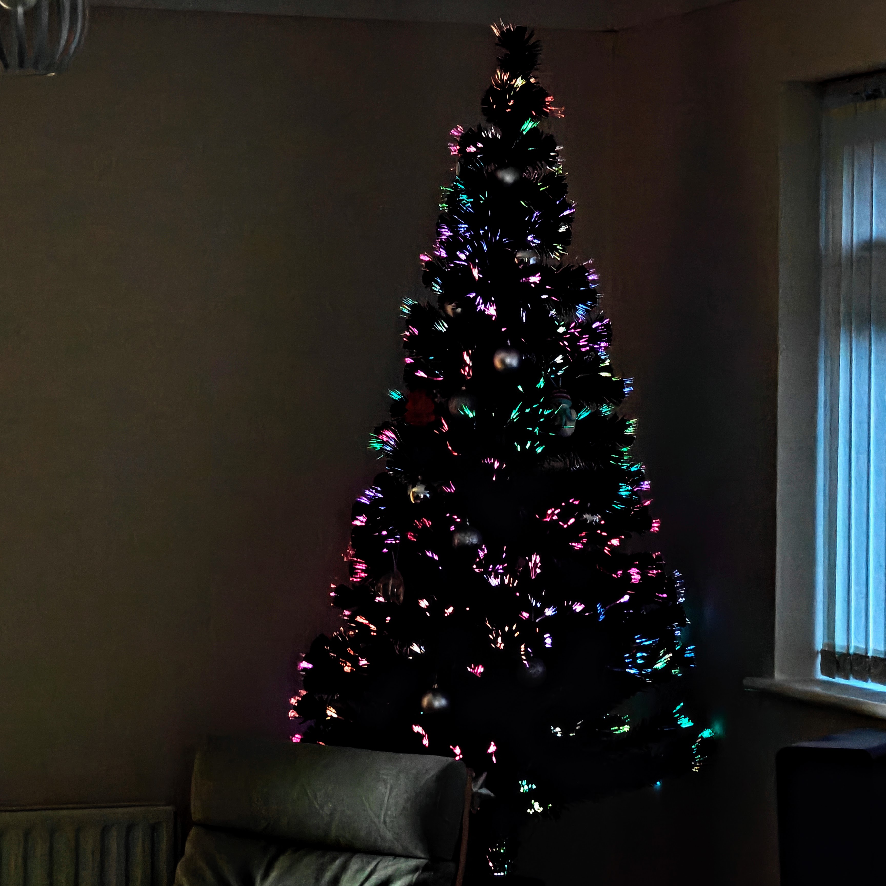
How much did this cost?
Prices per individual components from Amazon UK (bear in mind the LEDs and ESP boards are often only available in multiples). You can get these much cheaper if you are prepared to order from Aliexpress and have them shipped from China.
7 Segment LED Disc: £1.30
12 Segment LED Ring: £3.50
ESP32 D1 Mini: £6.69
3D printing < £1
Connectors < £1
Time including part design and printing: 1.5 hours.
A rubbish synchronous motor is a tenner. A good one £20+ so, I call that a saving and a functional upgrade. It's now brighter, uses less power and can be fully controlled by Home Assistant or the WLED app. It's also completely silent, which was the primary aim.
Comments